Product Description
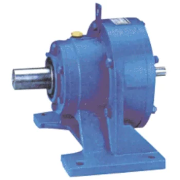
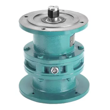
Frame Size 244mm 5r/m 1KW 250BX RVE Series High Precision Cycloidal Gearbox For Robot Arm
Model:250BX-RVE
More Code And Specification:
| E series | C series | ||||
| Code | Outline dimension | General model | Code | Outline dimension | The original code |
| 120 | Φ122 | 6E | 10C | Φ145 | 150 |
| 150 | Φ145 | 20E | 27C | Φ181 | 180 |
| 190 | Φ190 | 40E | 50C | Φ222 | 220 |
| 220 | Φ222 | 80E | 100C | Φ250 | 250 |
| 250 | Φ244 | 110E | 200C | Φ345 | 350 |
| 280 | Φ280 | 160E | 320C | Φ440 | 440 |
| 320 | Φ325 | 320E | 500C | Φ520 | 520 |
| 370 | Φ370 | 450E | |||
Gear ratio And Specification
| E Series | C Series | ||
| Code | Reduction Ratio | New code | Monomer reduction ratio |
| 120 | 43,53.5,59,79,103 | 10CBX | 27.00 |
| 150 | 81,105,121,141,161 | 27CBX | 36.57 |
| 190 | 81,105,121,153 | 50CBX | 32.54 |
| 220 | 81,101,121,153 | 100CBX | 36.75 |
| 250 | 81,111,161,175.28 | 200CBX | 34.86 |
| 280 | 81,101,129,145,171 | 320CBX | 35.61 |
| 320 | 81,101,118.5,129,141,171,185 | 500CBX | 37.34 |
| 370 | 81,101,118.5,129,154.8,171,192.4 | ||
| Note 1: E series,such as by the shell(pin shell)output,the corresponding reduction ratio by 1 | |||
| Note 2: C series gear ratio refers to the motor installed in the casing of the reduction ratio,if installed on the output flange side,the corresponding reduction ratio by 1 | |||
Reducer type code
REV: main bearing built-in E type
RVC: hollow type
REA: with input flange E type
RCA: with input flange hollow type
Application:
Company Information
FAQ
Q: What’re your main products?
A: We currently produce Brushed Dc Motors, Brushed Dc Gear Motors, Planetary Dc Gear Motors, Brushless Dc Motors, Stepper motors, Ac Motors and High Precision Planetary Gear Box etc. You can check the specifications for above motors on our website and you can email us to recommend needed motors per your specification too.
Q: How to select a suitable motor?
A:If you have motor pictures or drawings to show us, or you have detailed specs like voltage, speed, torque, motor size, working mode of the motor, needed lifetime and noise level etc, please do not hesitate to let us know, then we can recommend suitable motor per your request accordingly.
Q: Do you have a customized service for your standard motors?
A: Yes, we can customize per your request for the voltage, speed, torque and shaft size/shape. If you need additional wires/cables soldered on the terminal or need to add connectors, or capacitors or EMC we can make it too.
Q: Do you have an individual design service for motors?
A: Yes, we would like to design motors individually for our customers, but it may need some mold developing cost and design charge.
Q: What’s your lead time?
A: Generally speaking, our regular standard product will need 15-30days, a bit longer for customized products. But we are very flexible on the lead time, it will depend on the specific orders.
Please contact us if you have detailed requests, thank you !
| Application: | Machinery, Robotic |
|---|---|
| Hardness: | Hardened Tooth Surface |
| Installation: | Vertical Type |
| Layout: | Coaxial |
| Gear Shape: | Cylindrical Gear |
| Step: | Double-Step |
| Customization: |
Available
| Customized Request |
|---|

Calculation of Reduction Ratio in a Cycloidal Gearbox
The reduction ratio in a cycloidal gearbox can be calculated using the following formula:
Reduction Ratio = (Number of Input Pins + Number of Output Pins) / Number of Output Pins
In a cycloidal gearbox, the input pins engage with the lobes of the cam disc, while the output pins are engaged with the cycloidal pins of the output rotor. The reduction ratio determines the relationship between the number of input and output pins engaged at any given time.
For example, if a cycloidal gearbox has 7 input pins and 14 output pins engaged, the reduction ratio would be:
Reduction Ratio = (7 + 14) / 14 = 1.5
This means that for every 1 revolution of the input pins, the output rotor will complete 1.5 revolutions. The reduction ratio is a key parameter that influences the output speed and torque of the cycloidal gearbox.

Assembling and Disassembling a Cycloidal Gearbox
Assembling and disassembling a cycloidal gearbox requires careful attention to detail and precision. The process can vary depending on the specific design of the gearbox, but the general steps involve:
- Preparation: Gather all the necessary tools, components, and safety equipment for the assembly or disassembly process. Ensure a clean and organized workspace.
- Disassembly: To disassemble a cycloidal gearbox, follow these steps:
- Remove any external components or covers to access the gearbox internals.
- Identify and mark the positions of all components for reassembly.
- Release any locking mechanisms or fasteners that hold the gearbox components together.
- Remove each component carefully, starting from the outermost layers and moving inward.
- Cleaning and Inspection: Clean all components thoroughly using appropriate cleaning agents. Inspect each part for wear, damage, or any signs of degradation. Replace any components that are worn out or damaged.
- Reassembly: To assemble the cycloidal gearbox, follow these steps:
- Begin by assembling the internal components in the reverse order of disassembly.
- Apply lubrication to the gears and other moving parts as recommended by the manufacturer.
- Follow the markings made during disassembly to ensure correct positioning and alignment of components.
- Gradually secure each component with the appropriate fasteners, ensuring proper torque settings.
- Reattach any external covers or components that were removed earlier.
- Testing: After reassembly, perform functional tests to ensure that the gearbox operates smoothly and without any issues. Check for any abnormal noises, vibrations, or irregular movements.
- Final Checks: Double-check all fasteners, connections, and alignments. Verify that the gearbox functions as intended and meets performance specifications.
- Documentation: Keep detailed records of the assembly process, including torque settings, markings, and any adjustments made during reassembly. This documentation will be useful for future maintenance or repairs.
It’s important to note that cycloidal gearboxes can have complex designs, and the exact procedure for assembly and disassembly may vary. Always refer to the manufacturer’s documentation and guidelines for specific instructions related to your gearbox model.

Industries Benefiting from Cycloidal Gearboxes
Cycloidal gearboxes find applications in various industries where their unique characteristics are advantageous:
- Robotics and Automation: Cycloidal gearboxes are widely used in robotic systems for their compact design, high torque capacity, and precise motion control.
- Material Handling: Industries such as logistics and warehousing benefit from cycloidal gearboxes in conveyor systems due to their ability to handle heavy loads and provide smooth and accurate movement.
- Manufacturing: Equipment used in manufacturing processes, such as packaging machines and printing presses, often incorporate cycloidal gearboxes for their reliability and precise positioning.
- Aerospace: In aerospace applications, cycloidal gearboxes can be found in satellite systems, where their compactness and high torque-to-weight ratio are crucial.
- Medical Devices: Cycloidal gearboxes are used in medical equipment like robotic surgery systems for their precise movement capabilities and space-saving design.
- Defense: Military applications, such as remotely operated vehicles and surveillance equipment, benefit from cycloidal gearboxes’ ability to handle rugged conditions and provide precise control.
These industries leverage the advantages of cycloidal gearboxes to enhance the performance and efficiency of their systems.


editor by CX 2023-09-21